
Disclaimer: I work for Brocade, but the views expressed in this post are my own and don’t necessarily reflect the views of Brocade.
You might have heard about Ethernet Fabrics, or Brocade VCS Fabric technology. If you haven’t: don’t worry, this post will explain what it is and how it makes your life easier. I’ll also show you how to configure it.
Hint: it’s less than 2 lines of code per switch.
So, what is VCS?
Brocade VCS Fabric technology allows you to easily deploy a very scalable, easy to manage, self-healing network in your data centre. Yes, I was skeptical too when I first heard all those benefits in one sentence.
- Scalable: nobody is a fan of the Spanning Tree Protocol (STP) in the data centre. In a traditional environment, STP would block half of the links. Waste of expensive 10G/40G ports, and waste of money, really.
VCS allows you to add nodes on the fly, automatically adding bandwidth and additional ports.
- Elastic & self-healing: Scale up or scale down as you wish, the Ethernet Fabric will reconfigure itself automatically, which also happens if a switch fails or gets removed. There’s support for up to 32 switches in one VCS Fabric.
- Easy to manage: all switches in a VCS Fabric will form one logical chassis, making it very easy to manage and lowering OpEx costs. You manage the fabric from one principal switch, with distributed configuration for redundancy.
- Resilient: there’s ECMP multipathing for layer 1, layer 2 and layer 3. This is achieved through TRILL and FSPF, allowing for xx fully load-balanced Layer 3 gateways in your VCS Fabric which eliminates traffic tromboning. It allows for multi-hop FCoE as well, and best of all: you don’t have to rip & replace anything to get started as it’ll work with your existing Brocade/Cisco/Juniper and server infrastructure.
The picture on the left shows a classic access/distribution/core topology, with Spanning Tree Protocol in place blocking links, and the server not utilising all links as they have to be in active/standby mode.
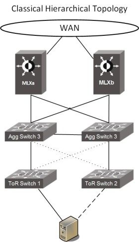
With Ethernet Fabrics in place (picture on the right), your access/distribution layer becomes one logical fabric. You can connect the switches in a ring, full mesh or leaf/spine, it’s all supported. We recommend using leaf/spine as it’s very scalable: just add more leaf nodes or links, and all VDX nodes will be automatically be added to the fabric, with all connected inter-switch links (ISL) active straight away to increase bandwidth. The devices connected at the edge (servers, or legacy switches) have no notion of the VCS Fabric and can utilise the standards-based 802.3ax LAG protocol to connect into the fabric. The picture below shows MLX as the WAN edge, but this would also work with Cisco or Juniper routers.
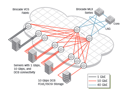
The topology above is what it looks like on a small scale, below is a picture that’s taken from the VCS Fabric Design Guide showing a larger fabric with a dedicated leaf for FCoE/iSCSI storage attached for example.
Sounds great, what do I need?
That’s an easy one: a VDX switch, which is Brocade’s flagship data centre switch with support for FC/FCoE built-in as well. VCS has been available for a few years on the VDX platforms, and the most current models are:
- VDX 6740: up to 64x 10G ports in a 1U form factor, or combo of 10G & 40G.
- VDX 6940: up to 144x 10G ports in a 1U form factor, or 36 x 40G.
- VDX 8770: modular switch allowing for 1G/10G/40G/100G connectivity.
It’s recommended to have an up-to-date version of NOS, the operating system on the VDX. Make sure the version is the same on all switches in the fabric.
To make VCS work, two things are needed: a VCS Fabric ID and a RBridge ID.
- The VCS ID defines the domain number of the fabric, and needs to be the same for all switches in a fabric.
- The RBridge ID defines the actual ID of the switch, and needs to be unique within a fabric.
It’s also recommended to set a management IP for the cluster, which is something you only have to set once.
By default, all links on a VDX switch are Fabric ISL links, which means they’ll automatically start forming an Ethernet Fabric if there’s a VDX switch connected to the other side.
Now, how do I configure this?
This is the easy part. Log in to your VDX switch through SSH, and type the following command:
RB101# vcs vcsid 10 rbridge-id 101 logical-chassis enable
In this case we set the VCS ID to 10, and the RBridge-ID to 101. The default for both is 1, and needs to be changed.
Once you set this command, the switch will reboot as it has to clear the current configuration database. The first switch will automatically become the principal switch, and the one that will be used for configuring the cluster.
Set the virtual IP address for the cluster on the principal switch, you only have to do this when you first setup the cluster:
RB101# conf t
RB101(config)# vcs virtual ip address 10.10.10.10/24
Now, repeat the first step for the other switches and you’re good to go! I’ve got 3 switches connected full mesh, so my setup is as follows:
RB102# vcs vcsid 10 rbridge-id 102 logical-chassis enable
RB103# vcs vcsid 10 rbridge-id 103 logical-chassis enable
Once the switches have been rebooted, you can check the status of your fabric by using the show fabric all command.
This shows there are 3 switches in our fabric, with 3x 10G links between. The principal switch is RB101, which is also the one that I’ve logged into here.
Another useful one is show fabric isl [all], or show fabric islports for more information:
This will give you an overview of the switches that the principal switch is connected to, use show fabric isl all to see details on all switches in the fabric.
Technical references:
- Ethernet Fabrics page on brocade.com (more links at the bottom)
- VCS Fabric Design Guide (PDF)
- VCS Technical Architecture (PDF)